Flash code to ESP8266 ESP-12 Module. Step-by-step guide
by Lord_evron
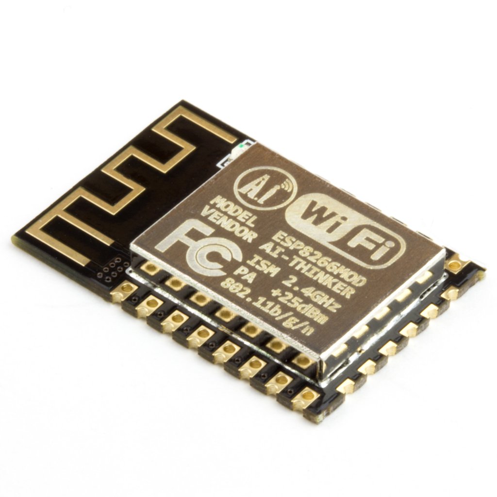
Recently, I stumbled upon a forgotten box in the shared hardware lab. Inside, amidst some clutter, I found a small chip module, about 1x2cm in size, labeled “ESP8266.” I initially assumed it was a spare part from a larger kit, perhaps unused by a previous lab member.
At first glance, it seemed like just another Wi-Fi module, commonly used to provide connectivity to Arduino boards. However, I noticed a few GPIO pins and a built-in antenna, suggesting the possibility of reprogramming the MCU and using it as a standalone module, much like an Arduino but significantly smaller. This intrigued me, and I decided to investigate further.
After some online research, I discovered a library developed by Espressif, the chip manufacturer, that included a function called wifi_send_pkt_freedom(). This was a game-changer! This function allows you to send arbitrary data over Wi-Fi, including custom-crafted low-level packets. The possibilities were exciting, ranging from creating fake access points to conducting de-authentication attacks (for educational and testing purposes only, of course!).
Let’s clarify a few things:
- The ESP8266 is the chip itself, produced by Espressif, which integrates an MCU, Wi-Fi module, and a full TCP stack.
- AI-Thinker is a manufacturer that produces various modules incorporating the ESP8266 chip. These modules, often referred to as ESP-XX, differ in pinout, dimensions, and integrated antennas.
- Development boards with integrated USB connectors are commonly used for ESP8266 development. However, my module lacked a USB connector. To connect it to my PC and flash the firmware, I needed an FTDI adapter, a common USB-to-serial converter.
Let’s now dig into the hardware connections.
HARDWARE
This is the pinout of the module.
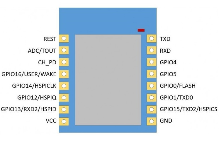
For flashing mode:
- SERIAL: You need a FTDI-USB converter (or a very old pc with a physical serial port 😀 (LOL I am so funny…) ) –> connect the FTDI_RX to TXD and the FTDI_TX to the RXD of the module.
- POWER: Supply the module with VCC->3.3V and GND.
- Gpio15: Connect the GPIO15 to GND using a 10 KOhm Resistor.
- Connect GPIO0 to Ground with a 10Kohm resistor. This make the ESP entering in FLASHING mode.
- If your chip has an ENABLE (or CH_EN) pull it High using a 10kohm resistor…(mine didn’t)</span>
Please notice that AFTER that GPIO0 is pulled LOW you must RESET the MCU for entering in Flash mode..
Unfortunately, despite I had all in place the flashing was still failing. After many attempt I suspected that had to be a power issue. So the FTDI chip WAS not ABLE to supply enough power for the flashing stage. So I used an external 3.3V (using the 3.3v output of an Arduino) and connected the FTDI ground together with the other grounds (leaving the 3.3V output of the FTDI disconnected). And Voila’ that was it…
SOFTWARE
The ESP can actually be flashed using the Arduino IDE but some more settings are required which i found on internet. In Particular:
- Go to File > Preferences
- Add Esp8266 Board to the Additional Boards Manager URLs. You can read more here
- Go to Tools > Board > Boards Manager and look for esp8266
- Select the version that best suite you and install.
Notice that if you want the "wifi_send_pkt_freedom()" than you must install the 2.0.0 . I tried with the latest version but does not work.. ALSO Notice that for using that functions more settings are required. I will have another Article explaining better what to do with code and such. This time we are just flashing “hello world” code…
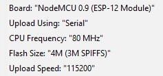
Well After this is done, from Tools–> Board you will see the ESP8266 sections.. You can either select the ESP12 or the generic. I have this settings:
Just select the correct COM/tty Port and should work!!! You can try flash any Arduino code…
ONCE that you Flashed the code, CHANGE GPIO0 to VCC and RESTART the MCU, so it will run the new firmware. If you do not switch to VCC, the module will still be in flash mode, and your code will not run on reset…
Obviously you can also Monitor the Serial Port to read the message printed by your code just like an Arduino!
If you experience problems make sure this two things:
- The MCU is properly supplied
- You remember to reset the MCU after switching GPIO0 to LOW/HIGH
Well that is it… Next time we will use this module to do some cool Stuffs!
tags: arduino - technology - ESP8266 - hardware